


Máquinas-ferramenta e máquinas de medição por coordenadas inevitavelmente mostram desvios sistémicos.
Para máquinas com três eixos cartesianos, esses desvios podem ser medidos com precisão pelo nosso método revolucionário TRAC-CAL e integralmente compensados.
As animações a seguir mostram os componentes de erro único. Os componentes de erro são listados com suas respectivas abreviaturas das normas (VDI 2617/ISO 230-1).
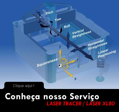
Position deviation in X-direction (XTX, EXX) (Laser XL 80)
Straightness deviation in Y-direction (XTY, EYX)
Straightness deviation in Z-direction (XTZ, EZX)
Pitch around Y-axis (XRY, EBX)
Position deviation in Y-direction (YTY, EYY) (Laser XL 80)
Straightness deviation in X-direction (YTX, EXY)
Straightness deviation in Z-direction (YTZ, EZY)
Pitch around X-axis (YRX, EAY)
Position deviation in Z-direction (ZTZ, EZZ) (Laser XL 80)
Straightness deviation in X-direction (ZTX, EXZ)
Straightness deviation in Y-direction (ZTY, EYZ)
Pitch around X-axis (ZRX, EAZ)
Squareness error between X and Y axes (XWY)
Squareness error between X and Z axes (XWZ)
Squareness error between Y and Z axes (YWZ)
Calibracao de dois eixos rotacionais na ferramenta
http://www.etalon-ag.com/downloads/Rotary_axis_calibration_of_tool.wmv
Calibracao de eixo rotacional no lado da peca (mesas rotatórias)
http://etalon-ag.de/downloads/Animationen/Trac-Cal_rotary_table_ver2.wmv
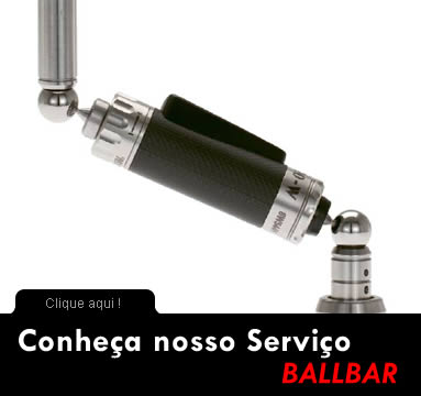
Abaixo algun stipos de falhas que podem ser diagnosticados em suas Maquinas-Ferramenta:
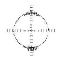
When an axis is being driven in one direction and then has to reverse and move in the opposite direction, instead of reversing smoothly it may pause momentarily at the turnaround point. This appears as short spikes that appear on either axis reversal point. This could mean servo response time is poor and excessive friction in axis.
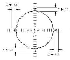
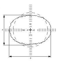
is shown as an oval plot, extended along one axis. One of the machine axes is either over traveling or under traveling relative to the other. One axis could be feeding too far or the other is not feeding far enough, possibly due to overheating or a faulty ballscrew. Servo loop gains may need adjustment.
If positive backlash it could be ballscrew end float, worn drive nut,or guide way play. If negative backlash the machine parameter might be overcompensated. If unequal backlash then there could be a wind up in the ballscrew where it becomes stiff on one end of the travel. It also typically occurs on a vertical axis and can also be caused by any counterbalance mechanisms or weight.
results when friction causes one axis to stick when it is fed at a very low rate. Left unchecked, this error could prevent the machine from producing an acceptable surface finish. Guideways or bearings could be bad or damaged. Improper lubrication or power can be supplied to overcome friction.
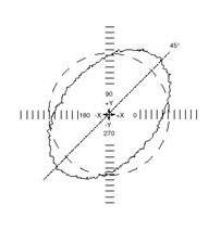
is shown in an oval ballbar plot It occurs when normally orthogonal axes are no longer moving at 90°, relative to one another. This may be due to a bent axis or some other misalignment. This squareness error oval tilts at 45° with respect to the two axes, and remains in the same position regardless of the direction of travel of the ballbar (CW or CCW).
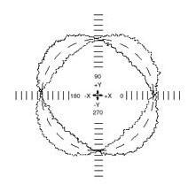
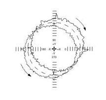
is shown as an oval plot tilted by 45° that does not stay in place - It shifts back and forth by 90° depending on the direction of travel. This indicates mismatched servo gains in the CNC, causing the axis with the higher gain to lead the other, and makes a precise circular interpolation impossible.

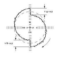
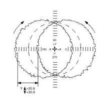
is shown as a plot with waviness that varies in amplitude and reaches a maximum amplitude at axis reversal. This error is caused by a flaw in the axis leadscrew or leadscrew mounting. If only in one half of plot on a vertical axis it may have to do with a counterbalance type problem.
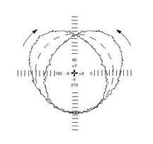
often results on CNC's that can only interpolate one axis at a time. Varying the speed of the master axis while the slave axis follows generates arcs. This changeover error produces a plot with 45° steps, and may make precision machining of circular features impossible.
is caused by looseness in the gibs or guide ways causing a fish tail effect. When machining interpolated holes you will tend to get an oval shaped hole.
These plots all tend to be setup errors with the ballbar equipment. The tool cup is either damaged, dirty, or walking out of the cup while running the test. It could be an error in the ballbar program you are running. It could also be the joints in the ballbar rods, cup or balls that are loose. It could also be that the computer is slow and not capturing quick enough.
Lack of straightness in machine guideways. They may be bent , misaligned, worn or poor machine foundation. Scaling error may be caused by scales encoder or drive.
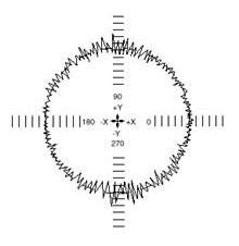
can be invoked by the machine itself, drive train, servo loop, damaged guideways or surrounding environment.

Economize milhões de reais realizando as manutenções preventivas de seus equipamentos