
What is an autocollimator? See how Volumetric runs this diagnostic
At Volumetric, autocollimator measurement is run by our team directly on your machine, and the raw reading is processed by the VCS (Volumetric Calibration System), our in-house diagnostic tool. Based on the real test data, the VCS:
- Reconstructs the pitch and yaw curves along the axis travel
- Integrates the measured angle to calculate equivalent straightness, when applicable
- Calculates the real squareness between the evaluated axes or surfaces
- Points out whether the correction is mechanical or falls within the range your control's software compensation can apply
The result is the diagnosis of the angular cause and the technical path to correction, with a real source behind every calculation: machine file, official manufacturer manual, or validated technical documentation.
Errors the autocollimator reveals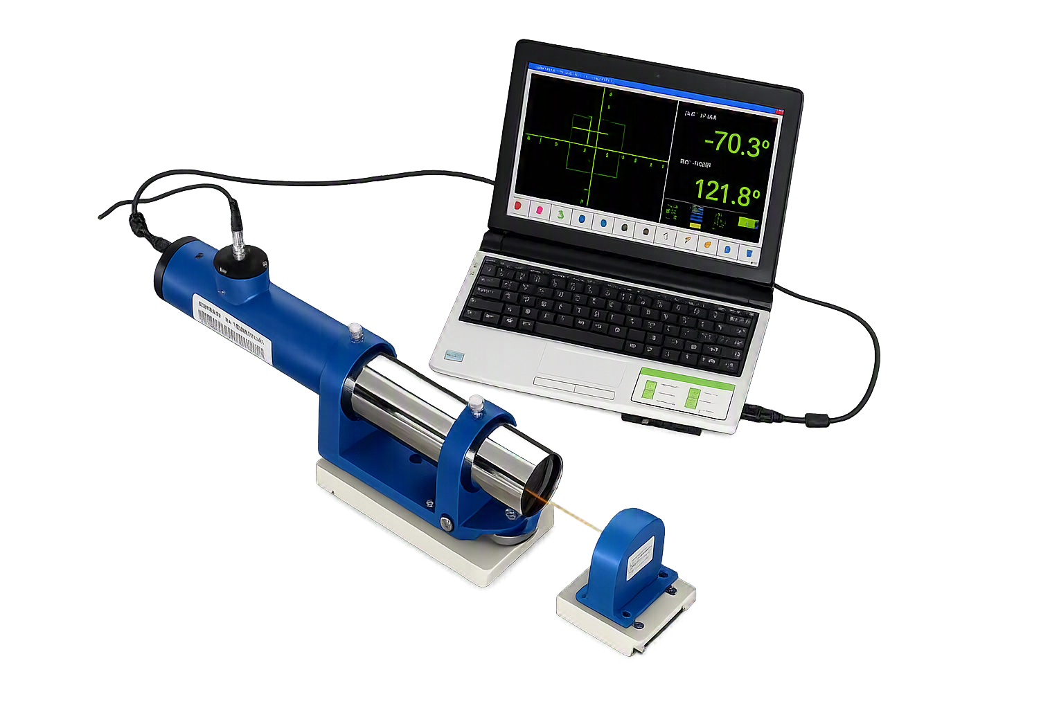
What is the autocollimator +
The autocollimator is an optical instrument that measures angular deviation without physical contact. It projects a collimated beam of light toward a reflector mirror mounted on the component being evaluated (the axis, the carriage, the table). The mirror reflects the beam back to the instrument, where a photodetector locates the return point; any angular tilt of the mirror shifts that point, and the autocollimator converts that shift into an angle. In electronic models, this reading is fully digital, with no optical eyepiece, with resolution reaching fractions of an arc-second in the highest-precision electronic instruments (1 arc-second is roughly equivalent to 4.85 µm per meter of distance).
Because it measures angle, not distance, the autocollimator sees a type of error that goes unnoticed by both circular testing and linear measurement: the rotation of one axis around the other two while it travels along its own path.
In practice, the mirror is mounted on the table or carriage, facing the direction of travel, and the autocollimator is aligned with it; the axis then moves continuously or in discrete steps while the instrument records the angle point by point. It's the same type of geometric test covered by ISO 230-1, which evaluates a machine's accuracy with no cutting load: straightness, squareness, parallelism, and angular deviations of linear and rotary axes.
What the autocollimator reveals +
With the mirror mounted on the moving axis and the autocollimator recording the angle along the full travel, the instrument allows you to evaluate:
- Pitch and yaw: axis rotation in the two planes perpendicular to its own travel
- Angular straightness: travel straightness calculated by integrating the measured angle, useful when physical access rules out other methods
- Squareness between axes and surfaces: the real angle between two directions of motion or between a face and the reference plane
- Flatness and twist of ways and tables: point-by-point angular variation over a surface that should be flat
This type of error usually shows up on the part as taper, funneling, or twist. Those symptoms have no obvious link to backlash. Only angular data explains them clearly.
How squareness and parallelism between guideways are measured +
To compare two guideways (for example, the two sides of a way or two parallel guideways on a large machine), the autocollimator first measures the straightness of one, which serves as the reference. A 90° prism is then positioned in the beam path to deflect it at exactly a right angle, allowing the second guideway to be measured using that same optical reference. Comparing the two straightness curves (one rotated 90° relative to the other for squareness, or overlaid directly for parallelism) yields the real deviation between the guideways.
For rotary axes and rotary tables, such as the axis used in RTCP testing on 5-axis machines, the autocollimator is combined with a polygon mirror mounted on the rotating axis: each mirror face reflects the beam at a different angle, and the instrument records the axis's angular positioning uncertainty at each stop. A precision indexing table also allows the polygon mirror itself to be calibrated before the test, isolating axis error from measurement-accessory error.
What the measurement doesn't do on its own +
The autocollimator delivers the axis's real angular profile, point by point. It doesn't indicate, by itself, whether the correction should be made with mechanical shims, a leveling re-check, way adjustment, or software compensation: that depends on the machine's architecture and on which of those paths the control (Siemens, Fanuc, Heidenhain, Mitsubishi, Mazatrol, Fidia) actually allows. Angular error too large for software compensation requires mechanical intervention, not a parameter.
When it's worth taking the measurement +
Autocollimator measurement is typically recommended:
- At technical acceptance of a new machine, or after relocation elsewhere
- Before buying a used machine, especially large ones
- After a collision, way overhaul, level re-check, or retrofit
- When parts come out with taper, funneling, or twist with no obvious cause
- As part of periodic preventive maintenance on long-travel machines, where the effect of a small angular error is amplified by distance
Angular error accumulates silently along the travel: the longer the distance the axis travels, the greater the effect of a deviation that, on its own, looks small.
A quick video showing how we identify and correct this type of error, right on the machine.